Full code checking can be performed on standard cold formed steel shapes, based on the following codes:
Note:
Cold formed shape properties are available in the database and the values are based on the AISI or manufacturer values, whichever is selected (See Cold Formed Steel Database). You may also input your own basic shapes and the properties will be calculated automatically.
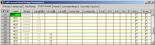
The Cold Formed tab on the Members Spreadsheet record
These parameters are defined for each cold formed member. The entries are explained below.
You may assign a unique Label to all of the members. Each label
must be unique, so if you try to enter the same label more than once you
will get an error message.
The member Shape or Section Set is reported in the second column. This value is listed for reference only and may not be edited as it is dictated by the entry in the Section/Shape column on the Primary tab.
The
See the Unbraced Lengths topic.
See the Unbraced Lengths topic.
See the Unbraced Lengths topic.
Cm Coefficients are described in Section C5 of the AISI code. If these entries are left blank, they will be automatically calculated.
The Cm value is influenced by the sway condition of the member and is dependent on the member's end moments, which will change from one load combination to the next, so it may be a good idea to leave these entries blank.
For the cold formed codes, Cb Coefficients are used in the calculation of the nominal flexural strength, Mn. If this entry is left blank, it will be calculated automatically.
The R Value for cold formed steel design is described in Section I6.2.1 of the AISI code and is used to calculate the moment capacity of beams that have one flange fastened to deck or sheathing. This value only applies to C or Z members and can vary from 0.4 to 0.7 based on the depth of the member (See Table I6.2.1-1 in the AISI Supplement for the actual values).
If a value is entered by the user, that value will be used by the program in the moment capacity calculation of the member. There are a number of restrictions that must be met to use this section of the code for moment capacity and the user is responsible to check that these restrictions are satisfied.
Note:
For double sections, the connector spacing 'a' is used in the calculation of the KL/r. There are also limitations on the connector spacing length that are checked.
The stiffness of gravity members will not be adjusted.
Access the Code Check spreadsheet
by selecting the Results menu and then selecting Members![]() Design Results or by clicking on the Design Results button on the Results toolbar.
Design Results or by clicking on the Design Results button on the Results toolbar.
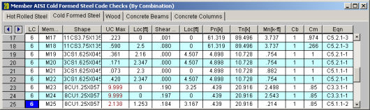
The final results of the code checking are the code check values UC Max and Shear UC. These values represent a factored ratio of actual to allowable load for ASD or ultimate load to design strength for LRFD or LSD, based on the provisions of Section H1. Section H2 is also used to check combined bending and shear. So, if this value is less than 1.0, the member passes. If it is greater than 1.0, the member fails. If the value is greater than 9.999 it will be listed as "9.999". The Shear Check is based on section C3.2.1. The Loc field tells at what location the maximum code check occurs measured from the I-joint location of the member. See Model Display Options – Members to learn how to view the code check results graphically.
The remaining columns, discussed below, provide some of the values used in the code check with the equation number itself given in the last column. The Member Detail Report gives more values used to perform the code check.
For ASD, the available strengths Pn/Omega, Tn/Omega, Mn
For LRFD or LSD, the values for factored compression Phi*Pn, factored tension Phi*Tn, factored moment Phi*Mn, and factored shear Phi*Vn are displayed.
Pn is calculated according to the provisions of AISI 2016, Chapter E. Tn is based on Chapter D. The Mn values are calculated based on Chapter F.
Cb will be calculated automatically if not specifically entered by the user, which is conservative. The Cm coefficients described in AISI S100-12 Section C5 and AISI S100-16 Section C1.2 are also listed. These also are influenced by the sway flag settings.
The final field lists the controlling equation for the code check. This will be one of the equations from Section H1 or H2.
For enveloped results, the combination that produced the listed code and shear checks is given in the column "LC". The other values are the corresponding values and are not necessarily the maximums across all the combinations.
The moving load results are enveloped and the governing load combination and step location is shown for each result value under the "LC" column. The first number is the load combination, the second is the step number: (load combination - step number). See Moving Loads to learn more.
The image below is the last portion of a detail report for a Cold Formed Steel member showing the member warnings, code checks, and section properties.
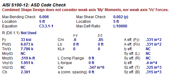
Below describes the Cold Formed Steel specific parameters. Refer to the Member Detail Report for more information on the values used to perform the code check.
Cw- Torsional warping constant. This will only be shown for Back-to-Back and Face-to-Face shapes. See Unbraced Lengths topic to understand how the bracing affects this calculation.
a (conn. Spacing)- distance between connections locations of built-up shape. This spacing is checked by code prescribed limits and is used in the calculation of KL/r. This will only be shown for Back-to-Back and Face-to-Face shapes.
A eff. (Fy)- The effective Area used in determining the nominal strength of the section, where the maximum stress is the yield stress.
A eff. (Fn)- The effective Area calculated at stress Fn, where Fn is the nominal buckling stress.
Iy eff. – The effective Moment of Inertia about the y-axis.
Iz eff– The effective Moment of Inertia about the x-axis.
Sy eff(L) - Effective section modulus about the Y axis for the extreme left fiber.
Sy eff.(R) Effective section modulus about the Y axis for the extreme right fiber.
Sz eff(T) - Effective section modulus about the Y axis for the extreme top fiber.
Sz eff.(B) - Effective section modulus about the Y axis for the extreme bottom fiber.
The effective properties listed above are based on the governing values used to determine the Mny and Mnz. The labels on the effective properties will al always state "Sy eff" however depending on the governing value it might be the fully unreduced section (Sf), effective section calculated relative to the extreme compression fiber at Fc (Sc) or effective section calculated relative to the extreme compression or tension fiber at Fy (Se).
When the Combined Tensile Axial load and Bending unity equations govern, the Detail Report will display the Sf. When the Combined Bending and Shear unity equations govern, the Detail Report will display the Se. When the Combined Compressive Axial load and Bending unity equations govern, the display depends if governing equations are: local yielding (Se), Lateral Torsional Buckling (Sc) or Distortional Buckling (Sf).
For all shape types, it is assumed that the transverse load on the member is occurring through the member's shear center. This means secondary torsional moments that may occur if the load is not applied through the shear center are not considered.
Iterations for the effective section modulus (Se and Sc) are ended when a difference less than 1% is achieved in the neutral axis distance calculation with a maximum of 5 iterations. Holes in sections are not considered in the shear strength calculations or for effective width calculations. Deflections are based on the full section properties, not the effective section properties.
Torsional warping effects are not included. Torsion stiffness and stress are calculated as pure torsion only. Web crippling is not considered.
See the Unbraced lengths for Cold Formed Steel section for the full details.
Kt in Section F2.1 is assumed to be 1.0.
Section C4.4 is not considered in the calculation of the axial strength at this time.
Z Shapes – The bracing length in Lbout is assumed to brace the minor principal axis. Z sections in compression are assumed to buckle in Euler buckling about their weakest principal axis. The value of rmin is used rather than the geometric rx and ry values.
H Shapes – Hat sections in bending about the y-y axis such that the brims are in compression are assumed braced such that the brims cannot each fail in lateral torsional buckling independently. For AISI S100-12 and older, lateral-torsional buckling is not checked for HU shape.
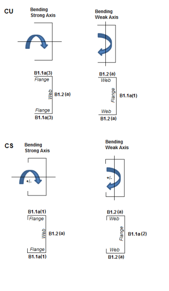
Slenderness Limitations - The w/t limits of Section B4 are enforced. However, the shear lag effects (Section B4.3) are not enforced. Below is an example showing the slenderness checks (AISI S100-12) for a CU and CS shape:
The distance between connector spacing is checked per smax (AISI Eq I1.1-1) however the spacing is considered uniform. The concentrated loads are not checked (AISI Eq I1.1-2) and there is no covered plate sections available (AISI Section I1.3).
The Slenderness ratio is altered based on the intermediate fastener spacing when applicable (AISI Eq I1.2-1). The Detail Report will display the modified KL/r if it governs. This modification is applied if the spacing meets the code limits that states a/ri does not exceed one-half the governing slenderness ratio of the member. The welds length and/or weld/fastener strengths are not checked in RISA (Section I1.2b,c). If the fastener spacing does not satisfy the aforementioned conditions, the global buckling stress of the built-up member is calculated based on the section properties of the individual stud members.
For Back to Back sections, the Weak Axis moments (My) or shear forces (Vz) for back-to-back shapes are not considered in the code check and this is noted in the Detail Report. The program will give you analysis information in the Detail Report and spreadsheets.
For Face to Face sections, the Torsional Constant (J) and Torsional warping constant (Cw) are calculated based on a tube shape if the Connector spacing is set to fully connected (a=0). If the connector spacing is greater than zero (a>0), the J and Cw calculation will be based on the summation of each element.
This message is displayed when the member is not defined with a database shape, or a steel code is not specified on the Model Settings, or no units were specified.
The ratio D/w exceeds the limiting criteria listed in Table B4.1-1 (AISI S100-16) or Section B4.2 (AISI S100-12) for simple lip stiffeners. (“D” and “w” are length of the stiffener and the flat length of the flange as defined in B4.2)
The angle (gamma) for a simple lip stiffener must be greater or equal to 40 degrees or less than or equal to 140 degrees per the criteria in Commentary Section 1.3 (AISI S100-16) or Section B4.2 (AISI S100-12). The angle gamma for this shape is outside this range.
The ratio w/t exceeds the limiting criteria listed in Table B4.1-1 (AISI S100-16) or Section B1.1 (AISI S100-12) for flanges. A value of 60 is used per the AISI code for unstiffened elements and elements stiffened with simple lips.
The ratio h/t exceeds the limiting criteria listed in Table B4.1-1 (AISI S100-16) or Section B1.2 (AISI S100-12) for webs. The program currently considers all webs as unreinforced, so a value of 200 is used as the limit.
The connector spacing "a" exceeds the limiting criteria listed in Section I1.1 (AISI S100-16) or Section D1.1 (AISI S100-12). The "L" in this equation is the beam span (full length of the member).